
Sometimes you want to play with electronic connections wirelessly. There are many examples using Bluetooth, Xbee, IoT etc; but most of them are pretty complex and before you get to what you really want to do there’s a lot of time needed just to get up the connection. Not to mention that you often need to involve microprocessors, phones or computers.
But if you just want to signal a button-press, light an LED or trigger a circuit far away, we have a simple solution:
RF Link Transmitter and Receiver 4 Channel – 433MHz
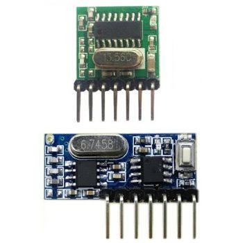
These wireless RF modules has 4 channels and work at 433MHz. They can easily fit into a breadboard and work well with microcontrollers or simple buttons to create a very simple wireless data link.
SPECIFICATIONS
- Transmitter module:
- Transmitting power: 11dbm
- Emission current: 10mA
- Rate of fire: maximum 10KB / S
- Operating Voltage: DC 3V-24V
- Encoding: EV1527 1527 Learning code
- Each module has a unique ID address code
- All modules K1-K4 four key code is the same
- Receiver module:
- Working Voltage: DC3.3~5V
- Quiescent Current: ≤5mA
- Output current: 10mA
- Working Frequency: 433MHz
- Receive Sensitivity: -108dB
- Working Temperature: -25~75
- Working mode: Momentary Mode , self-locking (Toggle-Mode of the 4 Channels) , interlocking
- The output: 4 channel CMOS level signal Corresponding to the remote control ABCD 4 buttons
FEATURES
- Remote control switch
- Receiver module
- Motorcycles, automobile anti-theft products
- Home security products
- Electric doors, shutter doors, windows
- Remote control socket, remote control LED, remote audio
- Remote control electric doors, garage door remote control
.jpg?1522065454980)
Using this stuff with Arduino
Here’s an example of how to have an Arduino send signals to light up LEDs on the receiving side:
To wire your RF 433 transmitter Module to your Arduino, connect the following pins:
- Connect the + pin to 5 Volts (5V)
- Connect the – pin to ground (GND)
- Connect the D1 pin to Arduino D4
- Connect the D2 pin to Arduino D5
- Connect the D3 pin to Arduino D6
- Connect the D4 pin to Arduino D7

The receiver:
- Connect the GND pin of your power supply to the breadboard – rail
- Connect the 5V pin of your power supply to the breadboard – rail
- Connect each cathode of the led to GND
- Connect D0 pin to led 1 anode via a 220 ohm resistor
- Connect D1 pin to led 2 anode via a 220 ohm resistor
- Connect D2 pin to led 3 anode via a 220 ohm resistor
- Connect D3 pin to led 4 anode via a 220 ohm resistor

Instructions and Code
- First power the receiver and press the button once. Then power the Arduino with the transmitter and upload the code. Now the Receiver and the transmitter are paired.
- Open the serial monitor and send any number between 0 and 7. 0 and 1 will toggle the first led on and off ,2 and 3 will toggle the second and so on.
- Also you can pair more that one receivers to a transmitter and vice versa and the will all work simultaneously.
/*
  RF Blink - Transmit sketch
     Arduino IDE version 1.0.5
     Website: http://arduinobasics.blogspot.com
     Transmitter: Tx-118s-4
     Description: A simple sketch used to test RF transmission with tx-118s-4 transmitter module
 ------------------------------------------------------------- */

 #define rfTransmitPin 4  //RF Transmitter pin = digital pin 4
 #define rfTransmitPin1 5
 #define rfTransmitPin2 6
 #define rfTransmitPin3 7
 #define ledPin 13        //Onboard LED = digital pin 13

 void setup(){
   Serial.begin(9600);
   pinMode(rfTransmitPin, OUTPUT);
   pinMode(rfTransmitPin1, OUTPUT);
   pinMode(rfTransmitPin2, OUTPUT);
   pinMode(rfTransmitPin3, OUTPUT);
   pinMode(ledPin, OUTPUT);
 }

 void loop(){

  char reply[50];
  int i = 0;
  if (Serial.available()){
  while (Serial.available()) {
    reply[i] = Serial.read();
    i += 1;
  }
   if(strlen(reply) > 0){

  int state=reply[0];
     if (state == '0') {
  digitalWrite(ledPin, LOW); // Turn LED OFF
  Serial.println("LED: Off"); // Send back, to the phone, the String "LED: ON"
  state = 0;
  digitalWrite(rfTransmitPin, LOW);
 }
 else if (state == '1') {
  digitalWrite(ledPin, HIGH);
  Serial.println("LED: On");
  state = 0;
  digitalWrite(rfTransmitPin, HIGH);
 }
 else if (state == '2') {
  digitalWrite(ledPin, HIGH);
  Serial.println("LED: Off");
  state = 0;
  digitalWrite(rfTransmitPin1, LOW);
 }
 else if (state == '3') {
  digitalWrite(ledPin, HIGH);
  Serial.println("LED: On");
  state = 0;
  digitalWrite(rfTransmitPin1, HIGH);
 }
  else if (state == '4') {

  digitalWrite(ledPin, HIGH);
  Serial.println("LED: Off");
  state = 0;
  digitalWrite(rfTransmitPin2, LOW);
 }
 else if (state == '5') {
  digitalWrite(ledPin, HIGH);
  Serial.println("LED: On");
  state = 0;
  digitalWrite(rfTransmitPin2, HIGH);
 }
  else if (state == '6') {
  digitalWrite(ledPin, HIGH);
  Serial.println("LED: Off");
  state = 0;
  digitalWrite(rfTransmitPin3,LOW);
 }
 else if (state == '7') {
  digitalWrite(ledPin, HIGH);
  Serial.println("LED: On");
  state = 0;
  digitalWrite(rfTransmitPin3, HIGH);
 }

  }

 }
 }
https://grobotronics.com/rf-link-transmitter-and-receiver-4-channel-433mhz.html?sl=en